|
Current Mirror:
The specifications
and technological parameters are given in figure 07. The calculated
design space for this set of specifications is shown in figure 08,
where the green line
represents the maximum allowable gain versus channel length for the
specified technological parameters. The red curve represents constant
cutoff frequency transistor and the blue line represents the maximum
inversion level. The yellow area represents the design space.
By selecting a
point, all its characteristics are displayed at the right side of the
screen.
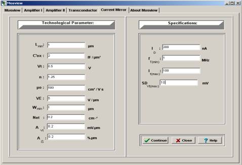
Fig. 07. Specifications and technological parameters for Current Mirror.
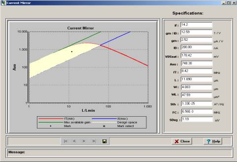
Fig. 08. Design space for the specifications of figure 07.
Amplifier I - Amplifier II - Current
Mirror - Tranconductor - CS Amplifier
|


