|
Amplifier II:
The specifications
and technological parameters are given in figure 03. The calculated
design space for this set of specifications is shown in figure 04, the
green line represents the maximum allowable gain versus channel length
for the specified technological parameters. The red curves represent
constant cutoff frequency transistors for fT= fT(min). The blue curve corresponds to fT = fTmax. The cyan
line represents the minimum drain current. The yellow region represents
the design space, i. e., the region for which the specs are met.
By selecting a
point, all its characteristics are displayed at the right side of the
screen.
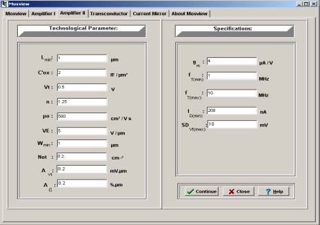
Fig. 03. Specifications an technological parameters for Amplifier II.
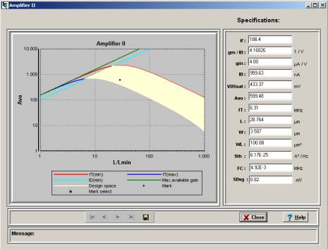
Fig. 04 Design space for the specifications of figure 03.
Amplifier I - Amplifier II - Current Mirror
- Tranconductor - CS
Amplifier
|


