|
Amplifier I:
The specifications and technological
parameters are given in figure 01. The calculated design space for this
set of specifications is shown in figure 02, the green lines represents
the maximum allowable gain versus channel length for the specified
technological parameters. The red
curve shows the variation of the gain in terms of the channel
length for fT= fTmax while the blue curve corresponds to fT= fTmin. The cyan line
corresponds to the minimum value for the voltage gain.
The
yellow region represents the design space, i. e., the region for which
the specs are met.
By selecting a point,
all its characteristics are displayed at the right side of the screen.
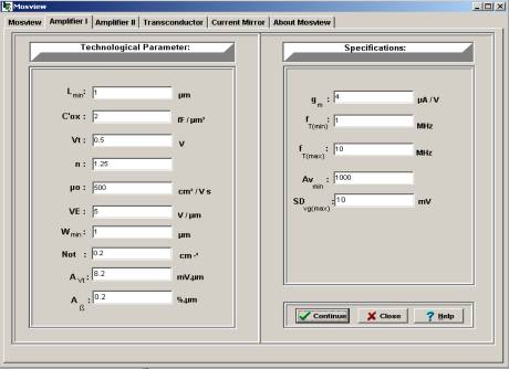
Fig.
01. Specifications and technological parameters for Amplifier I.
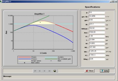
Fig. 02. Design space for the specifications of figure 01
Amplifier I - Amplifier II - Current
Mirror - Tranconductor - CS Amplifier
|


